Air Conditioner Refrigerant Structure Diagram:What does an air conditioner refrigerant structure diagram show?
Q: What does an air conditioner refrigerant structure diagram show?
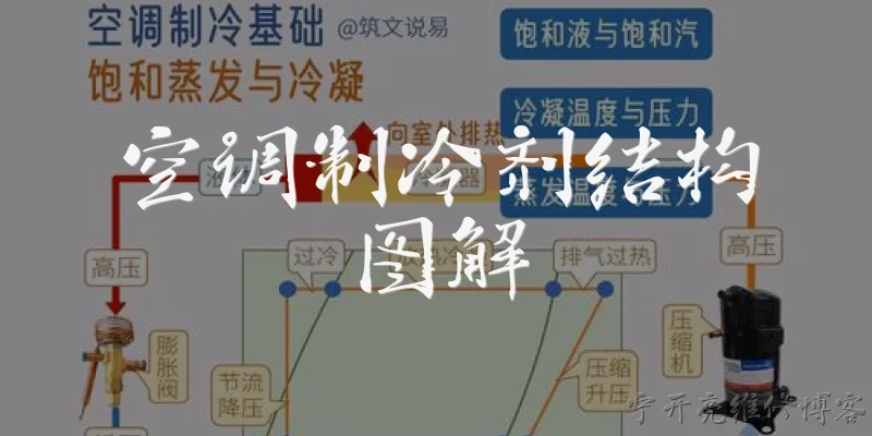
A: An air conditioner refrigerant structure diagram illustrates the closed-loop system through which refrigerant flows to transfer heat. It typically labels the compressor, condenser, expansion valve (or capillary tube), and evaporator, connected by copper lines. The diagram also shows the high-pressure and low-pressure sides, often with color coding (red for hot/high pressure, blue for cold/low pressure). Arrows indicate the direction of refrigerant flow: from the compressor as a high-pressure gas, through the condenser where it releases heat and becomes a liquid, then through the expansion valve where pressure drops and it partially vaporizes, and finally through the evaporator where it absorbs heat and returns to gas before re-entering the compressor. Some diagrams also include accessories like the accumulator, receiver-drier, or muffler, and may mark temperature and pressure points to help technicians diagnose issues.
Q: Why is it important to understand the refrigerant structure diagram when repairing an air conditioner?
A: Understanding the refrigerant structure diagram is crucial for effective air conditioner repair because it provides a roadmap of the entire sealed system. When a unit malfunctions—such as insufficient cooling or a refrigerant leak—technicians use the diagram to trace the flow and identify where the problem might occur. For example, if the low-pressure side is too low, the diagram helps narrow down causes like a clogged expansion valve or a leak in the evaporator. It also shows the location of service ports, so technicians know where to connect gauges and add refrigerant. Without this diagram, diagnosing issues becomes guesswork, risking damage to components or personal injury from high-pressure lines. Additionally, it helps in understanding how subcooling and superheat are measured at specific points, which is essential for proper charging and system efficiency.
Q: What are the key components labeled in a typical air conditioner refrigerant structure diagram?
A: A typical air conditioner refrigerant structure diagram labels the four main components of the refrigeration cycle: the compressor, condenser, expansion valve, and evaporator. The compressor is the heart, pumping refrigerant and raising its pressure and temperature. The condenser, usually a coil with fins, dissipates heat to the outside air, causing refrigerant to condense into a liquid. The expansion valve (or capillary tube) restricts flow, dropping pressure and allowing the refrigerant to expand and cool. The evaporator absorbs heat from the indoor air, boiling the refrigerant back into a gas. In addition, diagrams often label the accumulator (on the suction line) or receiver-drier (on the liquid line), service ports for gauges, and sometimes a muffler or oil separator. Arrows and color coding help distinguish high-pressure (red) and low-pressure (blue) sides, making the cycle easy to follow for diagnostics and education.
Q: How can I use a refrigerant structure diagram to troubleshoot common AC problems?
A: To troubleshoot AC problems using a refrigerant structure diagram, start by identifying the symptom and matching it to the diagram's flow. For instance, if the AC blows warm air, check the diagram to locate the low and high service ports. Connect manifold gauges: if both pressures are low, the system likely has a leak—use the diagram to inspect lines and connections for oil stains. If the low side is high and high side is low, the compressor may be faulty. If the high side is excessively high, the condenser might be blocked or the fan not working. The diagram also shows the expansion valve; if it's stuck closed, low side drops and high side rises. Always refer to the diagram to trace refrigerant path and compare expected pressures. This systematic approach saves time and prevents unnecessary parts replacement, ensuring you address the root cause accurately.
Dialogue about
Common scenarios of "Air Conditioner Refrigerant Structure Diagram"
【User】 Hey, can you help me understand the structure diagram of an air conditioner's refrigerant system?
【Expert】 Sure! The refrigerant system in an air conditioner consists of several key components: compressor, condenser, expansion valve, and evaporator. These are connected in a closed loop.
【User】 What does the compressor do in this system?
【Expert】 The compressor is the heart of the system. It compresses the refrigerant gas, raising its temperature and pressure, and pumps it to the condenser.
【User】 And what happens in the condenser?
【Expert】 In the condenser, the high-pressure hot gas releases heat to the outside air and condenses into a high-pressure liquid.
【User】 Then what's the role of the expansion valve?
【Expert】 The expansion valve controls the flow of refrigerant into the evaporator. It reduces the pressure, causing the refrigerant to expand and cool down significantly.
【User】 So the evaporator is where cooling happens?
【Expert】 Exactly. In the evaporator, the low-pressure liquid refrigerant absorbs heat from the indoor air and evaporates into a gas, thus cooling the room.
【User】 How are these components connected in the diagram?
【Expert】 They are connected by copper tubing, forming a continuous loop. The diagram usually shows arrows indicating the direction of refrigerant flow.
【User】 Are there any other important parts shown in the diagram?
【Expert】 Yes, there might be a filter drier, accumulator, and sometimes a reversing valve for heat pumps. These ensure proper operation and protect the compressor.
【User】 What is a filter drier used for?
【Expert】 A filter drier removes moisture and contaminants from the refrigerant, preventing blockages and corrosion in the system.
【User】 What about the accumulator?
【Expert】 The accumulator is located before the compressor and ensures that only gas, not liquid, enters the compressor, which could cause damage.
【User】 So the diagram helps technicians understand the flow and troubleshoot issues?
【Expert】 Absolutely. By following the diagram, technicians can identify each component, understand the refrigerant cycle, and diagnose problems like leaks or blockages.