TV switching power supply components:What are the key components of a TV switching power supply?
Q: What are the key components of a TV switching power supply?
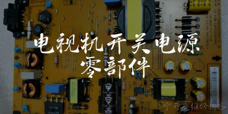
A: A TV switching power supply typically includes several critical components. The input section features a fuse, an EMI filter, and a bridge rectifier that converts AC to DC. The primary side contains a high-frequency switching transistor (often a MOSFET), a PWM controller IC, and a transformer that steps down voltage and provides isolation. On the secondary side, you'll find rectifier diodes, filter capacitors, and voltage regulators to produce stable DC outputs like 5V, 12V, and 24V. Additionally, feedback components such as an optocoupler and a TL431 reference maintain output regulation. Protection circuits, including overvoltage and overcurrent detectors, are also integrated. These components work together to efficiently convert and regulate power for the TV's mainboard, backlight, and other subsystems, ensuring reliable operation and safety.
Q: How do switching power supply components in a TV differ from those in a linear supply?
A: TV switching power supply components differ significantly from linear supply components in several ways. Linear supplies use bulky transformers operating at mains frequency (50/60 Hz), large filter capacitors, and linear regulators that dissipate excess power as heat. In contrast, switching supplies use high-frequency transformers (typically 20-100 kHz), allowing much smaller magnetic components. They employ fast-switching transistors (MOSFETs or IGBTs) and PWM controllers instead of linear regulators, achieving higher efficiency (often above 80%) and reduced size. The output rectification uses Schottky diodes for lower losses, and feedback is via optocouplers for isolation. While linear supplies are simpler and have lower noise, switching supplies are more complex but offer better efficiency, smaller footprint, and wider input voltage range, making them ideal for modern flat-panel TVs.
Q: What are common failure points in TV switching power supply components?
A: Common failure points in TV switching power supply components include electrolytic capacitors, which can bulge or leak due to heat and age, causing unstable voltages. The switching transistor (MOSFET) often fails shorted due to overcurrent or voltage spikes. The PWM controller IC may die from power surges or faulty feedback. Rectifier diodes on the secondary side can short, leading to no output. The optocoupler and TL431 reference can drift, causing incorrect voltage regulation. Solder joints on the primary side may crack from thermal cycling. Also, the startup resistor and snubber components can degrade. When troubleshooting, always discharge capacitors first. Replacing all suspect electrolytic capacitors with high-temperature rated ones is a common preventive measure. Testing with a multimeter and oscilloscope helps identify which components have failed.
Q: How can I test TV switching power supply components safely?
A: Testing TV switching power supply components safely requires caution due to high voltages. First, unplug the TV and discharge the primary filter capacitor using a resistor (e.g., 10kΩ, 5W) across its terminals. Use a multimeter to verify no voltage remains. For visual inspection, look for bulged capacitors, burn marks, or cracked components. Test diodes and transistors with a multimeter's diode mode: a good MOSFET shows a body diode drop, while a shorted one reads near 0V. Check capacitors with an ESR meter; high ESR indicates failure. For live testing, use an isolation transformer and a variac to gradually apply AC. Measure output voltages with a multimeter, but avoid touching the primary side. An oscilloscope can check PWM waveforms. Always work on a non-conductive surface and wear safety glasses. If unsure, consult a professional.
Words of experience
Common scenarios of "TV switching power supply components"
【Electrical Engineer】 Hi, I'm troubleshooting a TV switching power supply. I've got the schematic here. Can you walk me through the main components?
【Technician】 Sure! First, the AC input comes in through an EMI filter and a bridge rectifier. That converts AC to DC. Then you have a large bulk capacitor to smooth it.
【Electrical Engineer】 Right, I see a 400V 100µF cap. Next is the switching controller IC and the main MOSFET. How do they work together?
【Technician】 The controller IC drives the MOSFET gate with a high-frequency PWM signal. The MOSFET switches the primary winding of the transformer on and off, chopping the DC into high-frequency AC.
【Electrical Engineer】 So the transformer steps down the voltage and provides isolation. What about the secondary side?
【Technician】 On the secondary, you have rectifier diodes, usually Schottky or ultrafast, followed by filter capacitors and an inductor to smooth the output. There's also a feedback circuit using an optocoupler.
【Electrical Engineer】 I see an optocoupler and a TL431 shunt regulator. How does the feedback loop maintain regulation?
【Technician】 The TL431 senses the output voltage and drives the optocoupler LED. The phototransistor on the primary side sends a signal to the controller to adjust the duty cycle, keeping the output stable.
【Electrical Engineer】 That makes sense. What about the startup circuit? I see a high-value resistor from the bulk cap to the controller Vcc.
【Technician】 Yes, that resistor provides initial trickle current to charge the Vcc capacitor. Once the controller starts switching, an auxiliary winding on the transformer takes over and supplies Vcc.
【Electrical Engineer】 Got it. And the snubber network across the primary winding? I see a resistor, capacitor, and diode.
【Technician】 That's an RCD snubber to clamp the voltage spike when the MOSFET turns off. It protects the MOSFET from excessive drain-source voltage.
【Electrical Engineer】 What about the current sense resistor? It's a small value, like 0.1 ohm, in the source of the MOSFET.
【Technician】 That senses the primary current. The controller uses it for current-mode control and overcurrent protection. If the voltage across it exceeds a threshold, the controller shuts down.
【Electrical Engineer】 I also see a thermistor and a varistor on the AC input. Are those for protection?
【Technician】 Exactly. The varistor clamps voltage spikes from the mains, and the thermistor limits inrush current when you first plug in the TV.
【Electrical Engineer】 Thanks, that covers the main parts. One last thing: the output rectifier sometimes uses a synchronous rectifier instead of a diode. Is that common in modern TVs?
【Technician】 Yes, for higher efficiency, especially in slim TVs. A MOSFET replaces the diode and is driven synchronously to reduce losses. But it adds complexity.
【Electrical Engineer】 Great, I think I can debug this now. Appreciate the detailed explanation!
【Technician】 No problem! If you need help with specific voltage readings, just ask. Good luck!