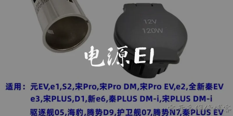
LED42K320 Power Board Schematic:What is an LED42K320 power board schematic and why is it important?
Q: What is an LED42K320 power board schematic and why is it important?
A: The LED42K320 power board schematic is a detailed electrical diagram showing the components, connections, and voltage rails of the power supply board used in Hisense LED42K320 televisions. It is important because it allows technicians to identify faulty parts, trace signal paths, and understand how the board converts AC mains into the DC voltages required by the mainboard, backlight, and other circuits. Without a schematic, troubleshooting becomes guesswork, and repairs are often limited to board replacement. The schematic also helps in checking standby voltage, PFC operation, and protection circuits, making it an essential tool for accurate and cost-effective repairs.
Q: Where can I find a reliable LED42K320 power board schematic online?
A: Reliable LED42K320 power board schematics are usually available on specialized TV repair forums, service manual websites, and some electronics document portals. Sites like Elektrotanya, Badcaps, and Russian repair forums often host Hisense service manuals that include power supply diagrams. You can also search using the exact board number printed on the PCB, such as RSAG7.820.XXXX, because the schematic is often shared under that identifier. Always verify the source and check user feedback before downloading, as incorrect or low-quality files can mislead repairs. Additionally, some paid databases offer guaranteed schematics, which may be worth it for professional technicians.
Q: What are the common failure symptoms that require using the LED42K320 power board schematic?
A: Common symptoms that require consulting the LED42K320 power board schematic include no standby light, no backlight, clicking sounds, dead TV, or intermittent shutdown. These often point to failures in the standby power supply, PFC circuit, or main voltage outputs. With the schematic, you can measure key test points like the 5V standby, 12V, 24V, and PFC voltage (around 380V) to isolate the faulty section. For example, if the 5V standby is missing, the schematic guides you to check the startup resistor, PWM controller, and feedback optocoupler. Without the diagram, such systematic diagnosis is much harder and slower.
Q: How do I read the LED42K320 power board schematic to troubleshoot a no-power fault?
A: To read the LED42K320 power board schematic for a no-power fault, start at the AC input and follow the path through the EMI filter, bridge rectifier, and PFC stage. Check the standby power supply section first, since it provides the 5V standby that enables the main power. Look for the PWM controller IC, its VCC pin, and the startup resistor. Next, verify the feedback circuit and the optocoupler. If the standby voltage is present but the main outputs are not, check the PFC voltage and the main PWM controller. The schematic shows expected voltages and component designators, so you can test each stage logically rather than randomly.
Q: Are there any precautions when using the LED42K320 power board schematic for repairs?
A: Yes, there are important precautions when using the LED42K320 power board schematic for repairs. The power board contains high-voltage capacitors that can retain dangerous charges even after unplugging. Always discharge the main filter capacitor and PFC capacitor before touching the board. Use an isolation transformer when testing live, and connect your meter's ground to the hot ground of the primary side, not the chassis, unless specified. Also, ensure the schematic version matches your exact board revision, as component values and layouts can change between production runs. Finally, never bypass protection circuits; they are there for safety and proper operation.
Words of experience
Common scenarios of "LED42K320 Power Board Schematic"
【Technician】 Hi, I'm working on an LED42K320 TV that won't power on. I suspect the power board is faulty. Do you have the schematic?
【Engineer】 Hello! Yes, I have the schematic for the LED42K320 power board. What specific information do you need?
【Technician】 Great! I need to check the standby voltage first. Where can I measure it?
【Engineer】 You can measure it at connector CN902, pin 1. It should be around 5V in standby mode.
【Technician】 I measured 0V there. What should I check next?
【Engineer】 Check the main fuse F901 and the bridge rectifier. If the fuse is blown, there might be a shorted component.
【Technician】 The fuse is good. I have about 160V across the main filter capacitor C907.
【Engineer】 That's normal. Next, check the startup resistor and the VCC pin of the PWM controller IC901. What's the voltage on pin 7 of IC901?
【Technician】 I get 0V on pin 7. Could the IC be bad?
【Engineer】 Possibly, but first verify the startup resistor R903 and R904 are not open. Also check the diode D905 and capacitor C910 in the VCC circuit.
【Technician】 R903 and R904 are fine. D905 and C910 seem okay too. Still no VCC.
【Engineer】 Then IC901 might be defective. It's a NCP1251. You can replace it and see.
【Technician】 I replaced IC901, but now the fuse blows immediately when I power on.
【Engineer】 There's likely a short in the primary side. Check the MOSFET Q901 and the snubber circuit around it.
【Technician】 Q901 is shorted between drain and source. What could have caused that?
【Engineer】 Often it's due to a faulty snubber or a bad PWM IC. Also check the current sense resistor R910 and the optocoupler IC902.
【Technician】 R910 is open. I'll replace Q901, R910, and IC901 again. Should I also replace the optocoupler?
【Engineer】 Yes, it's good practice to replace the optocoupler and the TL431 on the secondary side to prevent future issues.
【Technician】 Okay, I'll replace those. After that, what voltages should I expect on the secondary side?
【Engineer】 You should have 5V standby, 12V, and 24V for the backlight. Check them at CN902 and CN903. Let me know if you need further help.